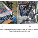
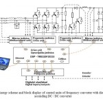
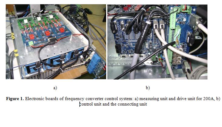
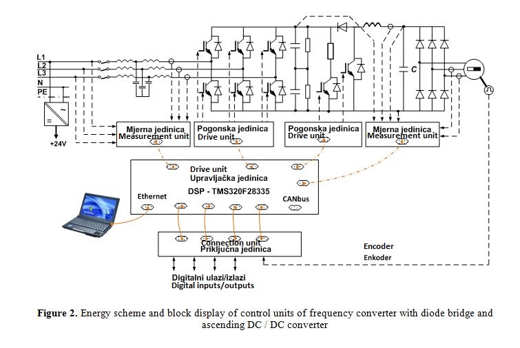
The prototypes of two structures of frequency converters for high-speed generators are being developed within the project. Although the structure of the converters partially differ in the power circuit and control algorithms, for both structures is used the same microprocessor control system that has been developed, manufactured and tested within this project. The control system consists of four electronic boards (control unit, measuring unit, driver unit, connection unit) that are block shown in Figure 2 in the framework of the structure of frequency converter based on the ascending DC / DC converter. All boards are made in a modern multi-layer SMD technology. Functional development of the boards, ie. defining schemes, is done within project activities by memebers of the research team, and development of lines and elements layout as well as producing few pieces of every board is entrusted to „Elmar“ company from Split.
Basic features of the electronic boards are:
- The control unit is a 6-layer board, which is based on a digital signal processor (DSP) type TMS320F28335 whose manufacturer is Texas Instruments. Except DSP-a, which consists all management-control alghoritms, within the control unit are conditioned analog measurement signals (16 AI), as well as input/output digital signals (8 DI, 8 DO, 12 PWM), and the board has several communication channels (CANbus, RS485, RS232, Ethernet).
- Measurement unit is a 4-layer, it processes analog signals for 4-channel voltage measurement, 3-channel current measurement and single-channel temperature measurement of IGBT modules. LEM power sensors type LV25 that are built in measurement board are used to measure the voltage, for current measurement are used LEM current sensors type HAT600 that are mounted on the cooler through which pass alternating bus with IGBT modules, and they are cable connected with measurement unit. Every IGBT module has resistive temperature sensor (NTC thermistor). At the measuring unit electronic circuit processes the temperature signals from the three IGBT modules so that it forms one output analog signal that is proportional to the temperature of the hottest of the three modules. All 8 measuring signals is transferred to the control unit via 9-pin shielded cable.
- The drive unit is a 4-layer, it transmits control signals to control IGBT transistors generated by the control unit. Control signals are formed and galvanically isolated from the control system, and also within it is realized protection from short circuit of IGBT modules by measuring the collector-emitter voltage during the state of keeping the transistor. Within the project two versions of the drive units were implemented, for current of IGBT modules up to 200 A and up to 600 A.
- Connection unit is 4-layer, it is a classic wire interface of frequency converter towards the process and a superior control system, and through it encoder for measuring the speed and position of the rotor of PM generator is connected.


